Design
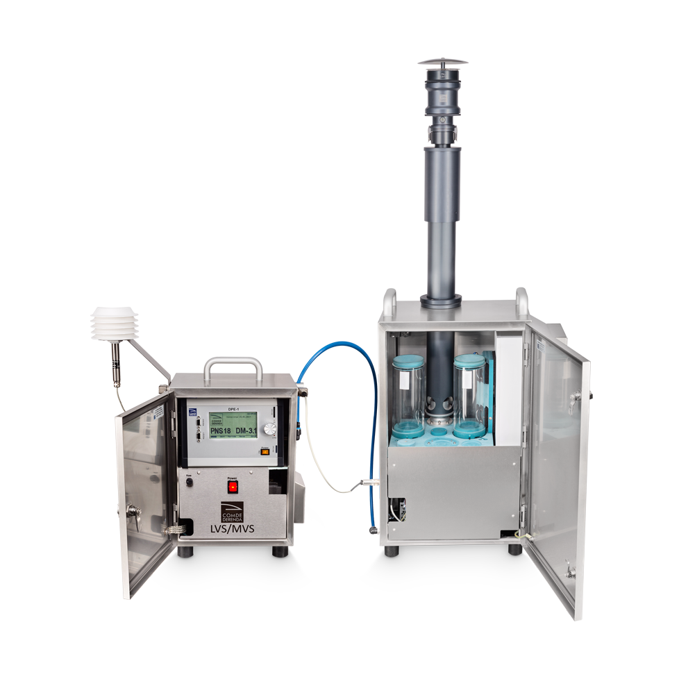
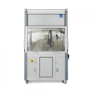
The sampling system PNS consists of a low / medium volume sampler (LVS or MVS) and an automatic filter changer. Before operation commences, the electrical and pneumatic connections are made between the two system components. The components consists of the following principal parts:
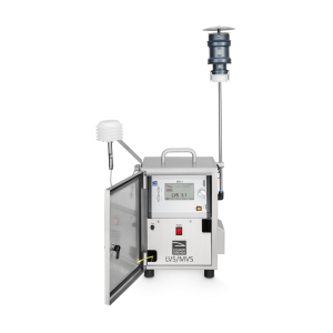
LVS /MVS:
- Stainless steel cabinet with lockable door
- Control unit with electronic modules, SD card reader and RS-232C interface
- Vacuum pump
- Orifice plate
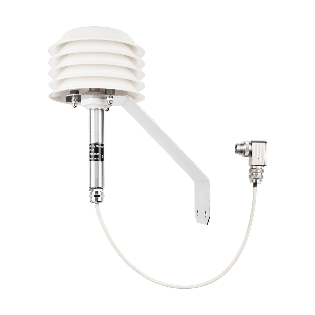
- Temperature and humidity sensors
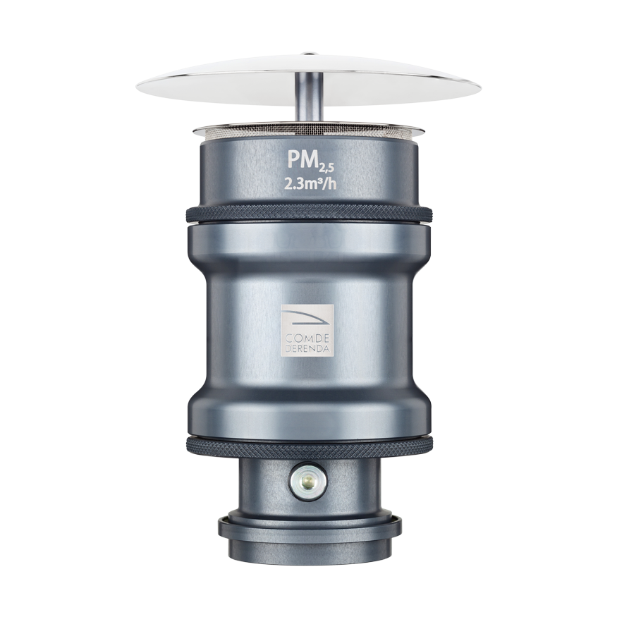
The LVS 3.1 is equipped with a 4 m³/h rotary vane vacuum pump. The volumetric flow rate for sampling PM10 or PM2.5 fractions is 2.3 m³/h; the maximum vacuum at the filter is 300 mbar. The maximum volumetric flow rate when glass fiber filters are being used is 3.5 m³/h. The LVS 3.1 is a reference device according to European standard EN 12341:2014.
The MVS 6.1 is equipped with a 8 m³/h rotary vane vacuum pump and is otherwise identical to the LVS 3.1. It can be operated with a maximum volumetric flow rate of approx. 5.5 m³/h. It is especially suitable for measuring semi-volatile organic compounds (SVOCs) and for use in conjunction with special filter materials (e.g. cellulose nitrate or Nuclepore filters). The maximum vacuum at the filter is 500 mbar. The MVS 6.1 is likewise a reference device according to European standard EN 12341:2014.
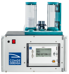
Automatic filter changer:
- Stainless steel cabinet
- Filter changer unit with Geneva drive and filter magazine holders
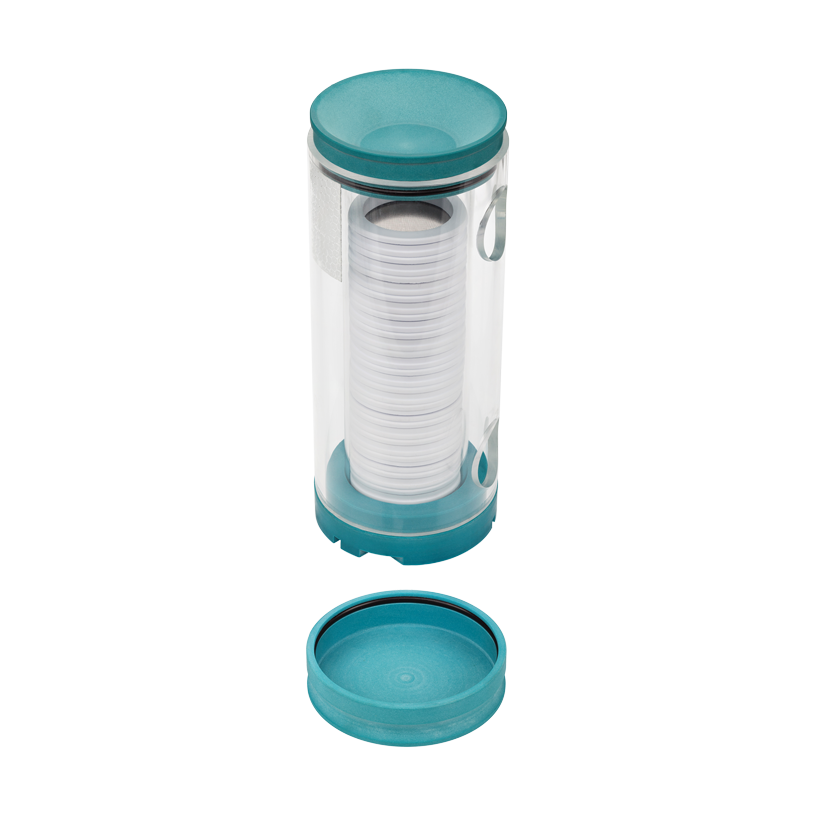
- 2 parallel filter magazines (capacity 18 or 24 filters each)
- Aluminum intake tube (anodized, polished inside, diameter 40 mm, length 800 mm, custom lengths available)
- Sampling inlet (for particulate matter fractions PM10, PM2.5, PM1 or TSP; optional)
- Peltier cooler (optional)
The filter changer cabinet is vented in order to prevent moisture condensation and icing-up of the filters. The connection between the sampling inlet and intake tube is gas-tight in order to prevent losses arising from particle deposits on the inside wall. Three magazines and 36 filter cartridges belong to each unit. When magazines are changed, one filter cartridge remains in the sampling position. The 18th resp. 24th filter is used not for sampling but as a reference filter to collect any passive particle deposits. The magazines also serve as portable containers.
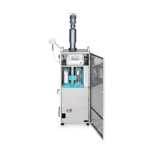
Operating principle
Before sampling begins, the desired settings are entered in the control unit, and the filter magazine is placed in the filter changer. Once the operating cycle is activated, sampling takes place automatically according to the set parameters. During operation the pump of the LVS/MVS draws in air laden with fine particulate matter through the sampling inlet of the filter changer. The dust particles are fractionated by size in the sampling inlet with impactor. The particles of the desired fraction are then deposited on the sampling filter in the sampling position. At the end of the sampling period, the changer automatically changes the filters as described below.
The filter changer uses two cylindrical magazines with a capacity of 18 or 24 filter cartridges each. The filter cartridges are arranged on top of each other in the magazine. Before use, either in the laboratory or in the sampling system, the magazines are loaded from the top. The left (holding) magazine contains the unladen filters. In the filter change operation, the unit transfers filter cartridges from the holding magazine to the sampling position. At the same time, the filter cartridge located in the sampling position and containing the laden filter is transferred to the right (sampled) magazine. The Geneva gearing allows the necessary complex movements to be performed simultaneously without any danger of collisions. A locking mechanism on the bottom of the magazines prevents the filter cartridges from falling out. For transportation purposes, the magazines have tight caps to prevent contamination by foreign particles. The magazine retains the top cap even while in use in the sampling system.
The volumetric flow rate is measured with an orifice plate and electronically adjusted with an accuracy of ≤ 2%. The ambient climatic conditions are continuously monitored by temperature and humidity sensors. The optional Peltier cooler ensures that the laden filter storage temperature in the unit does not exceed 23 °C.
The following data captured during sampling are saved in the internal memory. The data can be additionally backed up on an SD card or transferred to a PC by way of the RS-232 interface:
- Serial number
- Filter number
- Sampling start and end date/time
- Sampling duration in hours and minutes
- Mean volumetric flow rate in m³/h and Nm³/h
- Sampled volume in m³ and Nm³
- Mean air pressure/temperature/humidity
- Mean pressure difference at the filter
- Filter storage temperature
Detailed information on the LVS/MVS is contained in the respective datasheet.
The information on this website represents the state of knowledge at the time of writing. Technical specifications are subject to modifications. Comde-Derenda GmbH accepts no liability whatsoever for the content provided or for damages resulting from the use of its products.